Friday, September 18, 2020
Input Filters : Passive Filters
Variable speed drives
Altivar Process
Option: Passive filters
Passive filters are used to obtain total harmonic distortion of less than 10% or 5%. Reactive power increases at no load or low load. To help reduce this reactive power, the filter capacitors can be disconnected. Passive filters provide IP20 protection.
Applications : reduction of current harmonics in order to use drives in the first environment (restricted distribution, domestic applications).
Wednesday, September 16, 2020
Braking Resistors
Variable speed drives
Altivar Process
Option: Braking resistors
Altivar Process
Option: Braking resistors
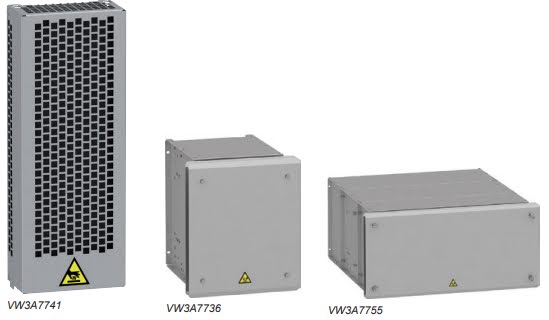
Braking resistors allow Altivar Process drives to operate while braking to a standstill, by dissipating the braking energy. They enable maximum transient braking torque.
Braking resistors are designed to be located outside the enclosure, but should not inhibit natural cooling. Air inlets and outlets must not be obstructed in any way. The air must be free of dust, corrosive gas, and condensation.
Several resistor models are available, depending on the drive rating:
- With IP20 and IP23 casing and thermal monitoring provided by temperaturecontrolled switch or by the drive
- The internal circuits of Altivar Process drives rated 220 kW/350 HP or less at 400...480 V and 45 kW/60 HP or less at 200...240V have a built-in dynamic brake transistor.
- An external braking unit is necessary for wall-mounting Altivar Process drives above 220 kW at 400...480 V as well as 55 kW/75 HP and 75 kW/100 HP at 200...240 V
Braking resistors are designed for a defined cycle (see the three cycle types defined below). Depending on your applications and cycles, you can use these resistors or define a new value:
- Braking resistors for light braking cycles for machines with cycles and inertia. The braking power is limited to 1.5 Tn for 0.8 s every 40 s.
- Braking resistors for medium braking cycles for machines with high inertia and conveyors. The braking power is limited to 1.35 Tn for 4 s every 40 s.
- Braking resistors for severe braking cycles for machines with very high inertia and vertical movements (hoisting). The braking power is limited to 1.65 Tn for 6 s and Tn for 54 s every 120 s.
Output filters : Sinus filters
Variable speed drives
Altivar Process
Option: Output filters Sinus filters
Sinus filters allow Altivar Process drives to operate with long motor cables:
- 500 m (1,640 ft) with a shielded cable
- 1,000 m (3,280 ft) with an unshielded cable
The minimum switching frequency at which sinus filters can operate is 4 kHz. This is the default value when the sinus filter function is activated on the variable speed drive.
The output frequency must be less than 100 Hz.
At 100% load, the voltage drop is less than 8% with output frequency 50 Hz and switching frequency 2 kHz.
For applications requiring:
- Long cable runs
- Motors connected in parallel
- Submersible pumps sensitive to dv/dt
- An intermediate transformer between the drive and the motor
Output Filters : dv/dt filters
Variable speed drives
Altivar Process
Option: Output filters
dv/dt filters
Altivar Process
Option: Output filters
dv/dt filters
Altivar Process drives with supply voltages of 200...240 V and 380...480 V operate with the following maximum motor cable lengths: 150 m/492 ft for shielded cables and 300 m/984 ft for unshielded cables. For a supply voltage of 500...690 V, maximum motor cable lengths are: 10 m/32 ft for shielded cables and 20 m/65 ft for unshielded cables.
To limit the impact of dv/dt and overvoltages in the motor, it is advisable to add an output filter if the motor insulation type does not conform to IEC 600034-25:
- For cables <50 m/164.04 ft, a dv/dt output filter
- For cables >50 m/164.04 ft, a sinus filter
Output filters are used to limit dv/dt at the motor terminals to 500 V/μs maximum for supply voltages up to 480 V, to 750 V/μs maximum for a supply voltage of 500 V, and to 1,000 V/μs maximum for a supply voltage of 690 V.
Output filters are designed to limit overvoltages at the motor terminals to less than:
- 800 V with a shielded cable 0 to 50 m (0 to 164 ft) long for a 400 V supply voltage
- 1,000 V with a shielded cable 50 to 150 m (164 to 492 ft) long for a 400 V supply voltage
- 1,500 V with a shielded cable 150 to 300 m (492 to 984 ft) long for a 400 V supply voltage (up to 500 m (1,640 ft) with an unshielded cable)
- 1,300 V for a 500 V supply voltage, cable length depending on the dv/dt filter combination
- 1,600 V for a 690 V supply voltage, cable length depending on the dv/dt filter combination
The performance of dv/dt filters will be affected if the maximum cable lengths are exceeded. For an application with several motors connected in parallel, the cable length must include all cabling. If a cable longer than that specified is used, the dv/dt filters may overheat.
The switching frequency must be less than 8 kHz.
Apa perbedaan Variable Frequency Drive (VFD) dan Variable Speed Drive (VSD) ?
- Variable Frequency Drive (VFD), merupakan pengontrol gerak (drive) yang bekerja dengan cara mengubah frekuensi dari sebuah Motor AC. VFD hanya untuk dihubungkan dan digunakan untuk Motor AC saja.
- Variable Speed Drive (VSD), merupakan pengontrol gerak (drive) yang bekerja mengubah kecepatan motor dengan memvariasikan nilai tegangan suplai, baik drive tipe tegangan AC ataupun DC. VSD terdapat pilihan AC drive dan DC drive.
Monday, August 31, 2020
Basic Setting atau Simply Start ATV Process (ATV630)
Basic Setting atau pengaturan dasar sangat diperlukan untuk pengoperasian setiap inverter. Oleh karena itu kami memberikan sedikit pengetahuan atau cara bagaimana melakukan pengaturan sebelum anda menggunakan ATV630.
Berikut ini adalah dasar pengoperasian atau setting ATV630 :
- Pastikan semua parameter motor atau pompa telah di inputkan pada ATV630 (berdasarkan spesifikasi motor) : => simply start => inputkan seluruh parameter motor => tekan ok
- Cara reset jika terjadi fault (dengan nyala display merah) : => complete setting => Error warning/handling => pilih fungsi mana yang terjadi error (co: input phase loss)
- Cara mengatur ATV default pabrik (riset) : File management => factory setting => parameter group list => pilih parameter yang ingin default pabrik /all parameter
- Cara mengganti local atau remote : My preferences => access level=> expert (mode) Complete settng => command & references => references configuration => Ref.freq.rem.terminal => HMI command => Bumpless
- Cara save parameter yang sudah di setting : File management => transfer config file => copy from to the drive/copy to the drive
- Cara modifikasi parameter : Complete setting => generic function => ramp
- Cara membuat simply start atau menu sendiri : My preferences => customization => My menu config
- Cara screenshot display : F1 + F4
- Cara preset speed (speed konstan) : => complete setting => generic function => preset speeds => pilih kecepatan
- Cara menentukan batas-batas kecepatan : => complete setting => generic function => speed limits => pilih low speed/high speed
Tuesday, August 25, 2020
eSetup Easergy Pro
Easergy P3 software for setting and configuration
eSetup Easergy Pro offers full facilities to set up Easergy P3 Protection relays. Intuitive and simple, eSetup Easergy Pro is a user-oriented interface to assist you during the engineering, commissioning and operation of Easergy P3 protection relays. Its streamlined workflow and graphical representations has been designed to simplify your configuration process.
Link Download :