In this article I would like to show you how to control an ATV320 variable frequency drive using Modbus serial port on M340 PLC. Before we begin, following is the list of items you need :
- PC with EcoStruxure Control Expert Small Software installed
- Schneider Electric Modicon (BMXP342020) PLC
- Schneider Electric Altivar ATV320 (ATV320U07M3C)
- SoMove, Drive Commissioning Software
- Schneider Electric Drive Programming Cable (TCSMCNAM3M002P)
- Schneider Electric USB Programming Cable (TCSXCNAMUM3P)
Before we look into the programming of ATV320 and M340 PLC, let us take a look at Modicon M340 PLC and Altivar ATV320 variable frequency drive.
A. M340 PLC
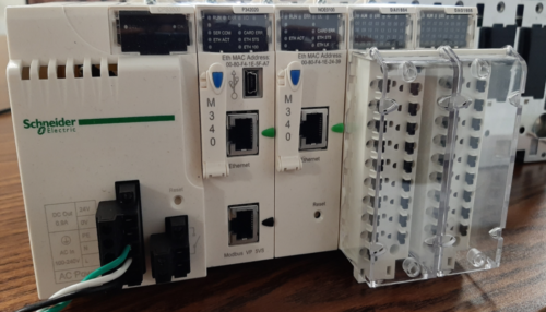
Modicon M340 is one of the Programmable Automation controllers (PAC) that Schneider Electric offers. It is built as all in one controller approach and can cater to wide range of demanding automation applications.
It comes built in with USB port for programming and HMI (Human Machine Interface) and two additional ports as required: Ethernet, Modbus, CANOpen. EcoStruxure Control Expert software is used for programming and commissioning of this controller.
B. Altivar ATV320
This family of Altivar drives is specifically designed to cater to Original Equipment Manufacturers (OEM) applications with horsepower range from 0.25hp to 20hp.
It is available in two form factors, book and compact. It comes with embedded safety such as STO (Safe Torque Off) and can support different communications such as Ethernet/IP and Profinet using option cards.
Step by Step Procedure to Integrate ATV320 drive with Modicon M340 PLC
Step 1:
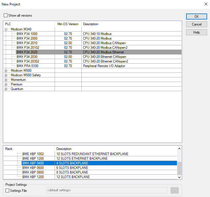
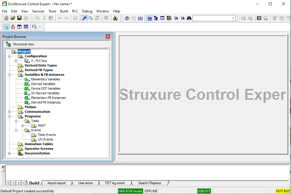
Create a new project in EcoStruxure Control Expert Small or Extra Large:
Select the processor BMXP342020 under Modicon M340, and rack BMXXBP0400:
Step 2:
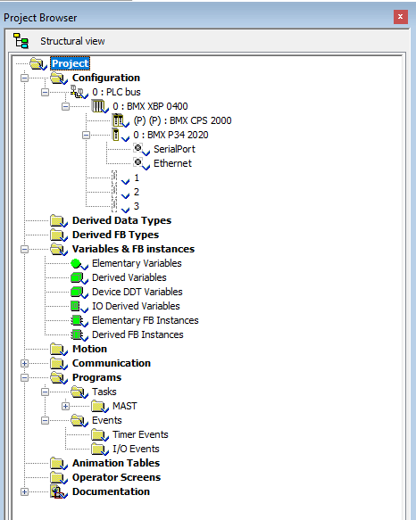
In Project Browser, navigate to Configuration and expand the tree to access Serial Port. Double Click Serial Port to modify the settings:
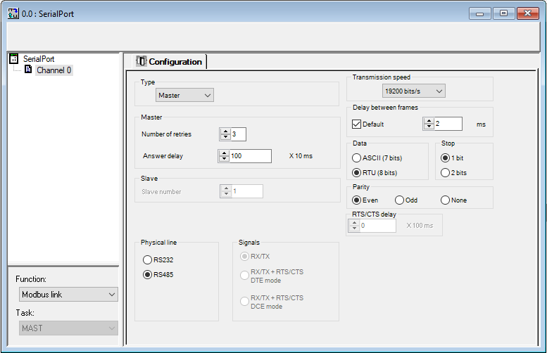
Configure the port as Modbus Master as shown below:
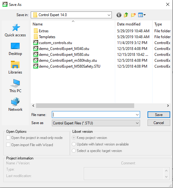
Do not forget to save your project.
Step 3
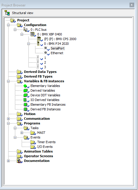
In this step, you will need to define array data structures that you can use to read and write data from drive to PLC and vice versa. You will access Variables & FB Instances in Project Browser window as shown below.
You will need to use Read_Var and Write_Var instructions in the program to exchange data between PLC and drive.
These instructions require slave address defined as input to these instructions. ADDM function is used to convert a character string into an address that can be used by the communication functions such as Read_Var and Write_Var.
You will use ADDM function to set ATV320 as slave device at address 1 and can connect upto 32 slave devices if needed. This tutorial refers to only one slave device.
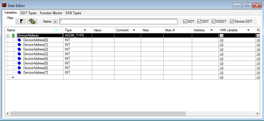
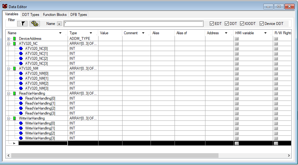
Define a DeviceAddress array of type ADDM_TYPE as shown below:
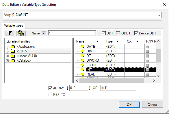
Then create four more arrays of INT(Integer) data type of size 4:
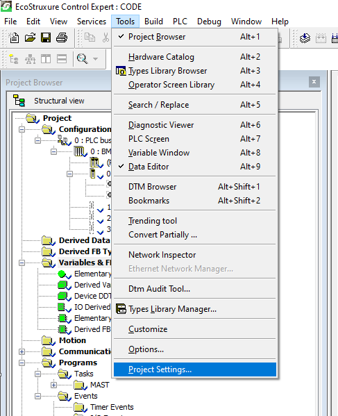
To achieve this, you will have to go on menu bar and select Project Settings under Tools:
Select Variables and enable Directly represented array variables as well as Allow Dynamic arrays (ANY_ARRAY_XXX):
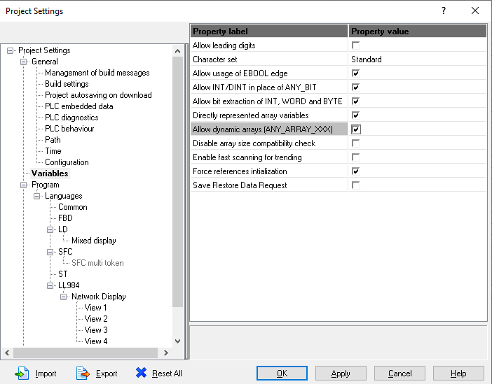
Click Apply and then OK.
Step 4
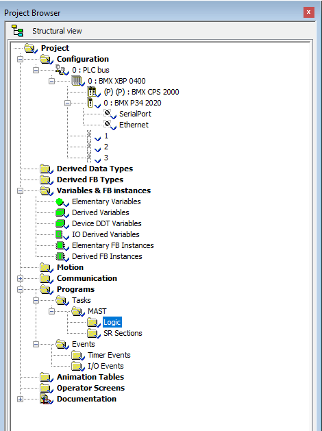
In this step you will need to write the program in Mast section. Right click on Logic and select New Section.
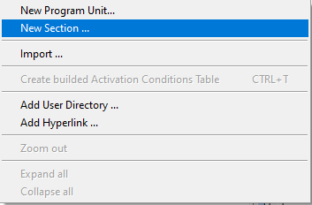
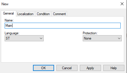
A new section window will open up. You will need to give it a name like Main and select programming language. In this tutorial, I have selected ST (Structured Text).
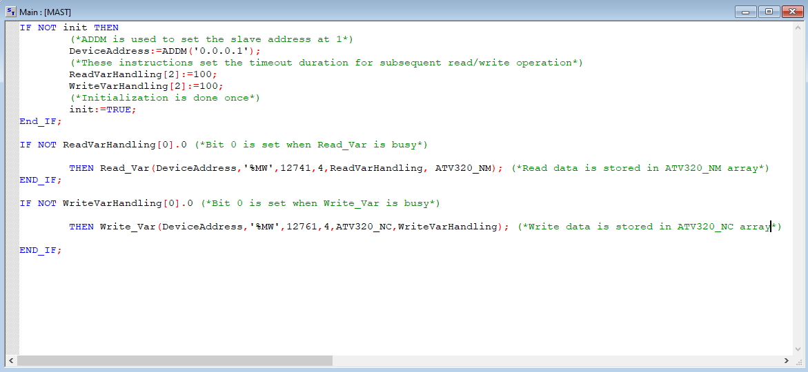
Type in the following code in Main section.
Save your project.
In the above code, the application manages two requests: A read request of four words starting at Modbus address 12741 (31C5 hex,) and a write request of four words starting at Modbus address 12761 (31D9 hex).
First two read words are mapped to Status Word and Output Speed of the drive.
Similarly, first two write words are mapped to command word and speed reference of the drive.
Step 5
From menu bar, select Build and choose Analyze Project to compile your project:
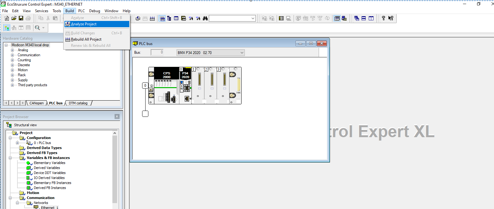
The project should build with no errors.
Next you will need to download program to the PLC. Select Connect under PLC on menu bar provided that you have connected PC and PLC via Schneider USB programming cable:

I have used Simulator running at 127.0.0.1 for this tutorial. You will see status as DIFFERENT and NO CONF since no configuration have been transferred to PLC and applications in PC and PLC are different.
Select Transfer Project to PLC or use CTRL+L on keyboard to load application into PLC:
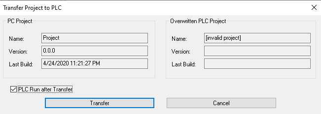

The application is now loaded, and PLC is in RUN mode.

Connect the PLC and drive via patch cord.
Step 6
In this step you will need to configure the ATV320 drive so it can communicate over Modbus via its communication scanner.
It is recommended to factory reset your drive before you do any configurations.
Factory Reset
To perform a factory reset from power up, enter the following on the dial:
- Scroll down to CONF menu and enter.
- Scroll down to FCS- and enter.
- Scroll down to FRY- and enter.
- Select All so that ” mark is at top instead of bottom.
- Now go to GFS parameter.
- Set it to yes and hold for 2 seconds until it goes back to GFS when you let go.
Command Settings
To control the drive with Modbus Master, you will have to select Modbus as active command channel. This can be achieved by selecting the following options from the face of the drive.
Enter on dial:
- CONF>FULL>CTL->Fr1> [MODBUS] MdB
- Set the command channel to Modbus
- CONF>FULL>CTL->Cd1> [Modbus] MdB
- You will also need to set the channel profile to I/O Profile.
- CONF>FULL>CHCF> [I/O Profile] IO
Communication Settings
Select the following
- CONF>FULL>COMM->Md1>Add>1
- CONF>FULL>COMM> [Modbus Baud Rate] tbr > [19.2 kbps] 192
- CONF>FULL>COMM> [Modbus Format] tFo >[8-E-1] 8 E 1
- CONF>FULL>COMM> [Modbus time out] tto > 10s
Power cycle the drive to make changes effective.


0 comments:
Post a Comment