Tuesday, November 24, 2020

Cara Upload Program Modicon M340 Menggunakan Unity Pro

 Catatan: Upload program tidak akan mengganggu konfigurasi atau sistem yang sedang berjalan, jadi aman. Proses ini dapat dilakukan saat PLC Run atau Stop.

Berbeda dengan Siemens, upload program dari Modicon ini mempunyai comment, jadi dapat dibaca.

  1. Gunakan kabel USB dan pilih PLC->Set Address, kemudian isi bagian PLC seperti gambar berikut, kemudian klik ‘Test Connection’. Jika berhasil, maka komunikasi sudah terjalin antara komputer kita dengan PLC.

set-address-modicon2. Klik icon ‘Connect’, kemudian klik icon ‘Upload’

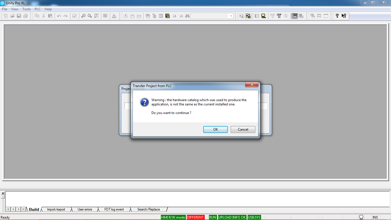
icon-connect-dan-upload-project3. Pilih ‘Transfer Project from PLC’

upload-program-modicon-m340_14. Yes

cara-upload-program-modicon

cara-upload-program-unity-proProject akan memulai proses upload, dan program sudah tersimpan. Selesai.

Share:

Cara Konfigurasi dan Komunikasi PLC Modicon M340 dengan SCADA Vijeo Citech

 Software yang digunakan Unity Pro XLS untuk konfigurasi PLC Modicon.konfigurasi plc modiconNote: Jika tidak mengetahui IP Address dari CPU, langkah pertama yang harus dilakukan adalah mengkoneksi PLC dengan kabel USB.
Konfigurasi PLC
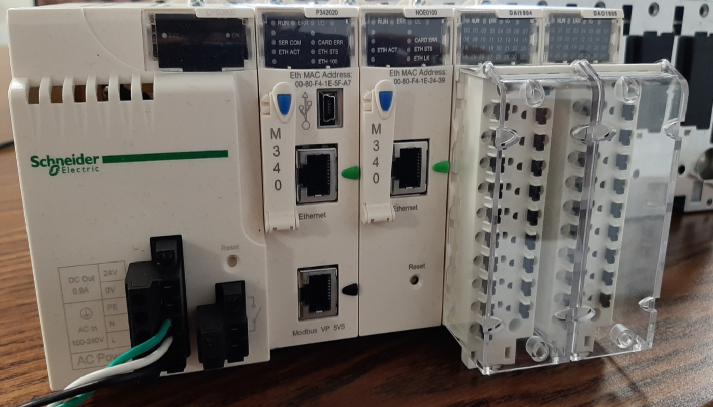
Masukan CPU beserta modulenya sesuai dengan hardware.
Kemudian untuk setting komunikasinya. Pilih Communications-> Network (Klik Kanan, new network). Kemudian setting IP Addressnya sesuai yang diinginkan.setting IP Address modiconKemudian kembali lagi ke konfigurasi network. Pilih ethernet, lalu assign ethernet yang sudah dibuat tadi.setting ethernetPada menu toolbar, pilih PLC -> set address. Lalu masukan IP Address sesuai settingan yang telah dibuat. Konfigurasi PLC sudah selesai, sekarang PLC sudah terhubung dengan komputer dan dapati di download program.setting addressset ip addressvariable modiconKonfigurasi SCADA Vijeo Citech
Communications-> Express I/O Device. Kemudian pilih external I/O Device, lalu pilih model Schneider Electric->M340->Modbus/TCP (Ethernet). Masukan IP sesuai denga IP PLC yang telah di konfigurasi (biarkan port bernila 0). Lalu click next sampai finish.express vijeo citectexpress vijeo citect porttag vijeo citect portKemudian buat graphic sederhana dan tagnya. Kemudian online, dan hasilnya akan terlihat bahwa PLC sudah terkonek dengan SCADA.
Catatan : Untuk alamatnya hanya bisa menggunakan %M, dan tidak dapat menggunakan I ataupun Q.
Share:

Belajar Dasar PLC Modicon M340 dan Unity Pro Schneider Eletric

 Software 

PLC yang akan dibahas adalah PLC Modicon M340 dengan menggunakan software Unity Pro XL V8.0 – 131118

Konfigurasi Hardware dari gambar diatas adalah sebagai berikut:

CPS 2000

P34 2020

BMX DDI 1602

BMX DDO 3202K

BMX DDO 3202K

BMX AMI 0410

BMX AMO 0802


Address dari DI, DO, AI dan AO

Berbeda dengan PLC lainnya seperti Siemens. Alamat Address dari masing-masing DI, DO, AI dan AO mempunyai ciri khas tersendiri, yakni akan tergenerate secara auto, berdasar konfigurasi hardwarenya. Mari liat gambar dibawah:

konfigurasi modicon

Jika kita lihat gambar di atas, maka urutannya adalah sebagai berikut:

[ 0 ] CPU

[ 1 ] Digital Input ( %IX.Y.Z )

[ 2 ] Digital Output ( %QX.Y.Z )

[ 3 ] Digital Output ( %QX.Y.Z )

[ 4 ] Analog Input ( %IWX.Y.Z )

[ 5 ] Analog Output ( %QWX.Y.Z )

Jadi, formatnya sama yakni X.Y.Z, dimana:

X : nomor racknya, contoh diatas berarti 0

Y : nomor urutan modul, contoh diatas untuk Digital Input 1

Z : nomor address di dalam modul, misal DI diatas punya input 16 buah. Berarti Z dapat diisi nilai 0-15.

Hal ini, juga berlaku juga untuk analog input dan analog output ya.

Wiring Diagram

Digital Input – BMX DDI 1602

wiring-bmx-ddi-1602

Digital Output – BMX DDO 3202K

wiring-bmx-ddo-3202K

Analog Input – BMX AMI 0410

wiring-bmx-ami-0410

Analog Output – BMX AMO 0802

wiring-bmx-amo-0802

Unity Pro

Pertama tentunkan CPU dan racknya terlebih dahulu:

unitypro

Sehingga akan muncul tampilan seperti ini:

layout-unitypro

Fokus pada panel Project Browser yang ada di sebelah kiri:

  1. Untuk masukan modul-module lainnya ada di menu configuration
  2. Untuk masukan variabel tag ada di menu variables & FB insttances
  3. Untuk mengatur komunikasi ada di menu communication
  4. Untuk membuat program ada di menu program
  5. Untuk simulasi variabel tag ada di menu animation tables

Unity pro juga mempunyai fitur simulasi, jadi program yang telah dibuat dapat disimulasikan dengan tombol yang ada di sebelah kanan atas. Sebelumnya cek komunikasi terlebih dahulu lewat menu toolbar di atas, PLC -> Set Address…

Sebetulnya masih banyak yang dapat digali di software ini. Mudah-mudahan nanti ada waktu ya.

Share:

Cara Koneksi PLC CPU to CPU Schneider Modicon M340

Untuk komunikasi CPU to CPU membutuhkan module tambahan, yakni NOE. Konfigurasi yang digunakan adalah CCR akan menjadi pusat pertukaran data, sehingga MTB6 sampai dengan MTB8 akan bertukar data melewati CCR. Berikut gambar screenshootnya.

modicon m340konfigurasi plc modicon

IO Exchange CCR

IO Exchange CCR

IO Exchange MTB8

IO Exchange MTB8

IO Exchange MTB7

IO Exchange MTB7

IO Exchange MTB6

IO Exchange MTB6

IO Exchange MTB5

IO Exchange MTB5

Share:

How to control an Altivar ATV320 VFD over Modbus with a Modicon M340 PLC

    In this article I would like to show you how to control an ATV320 variable frequency drive using Modbus serial port on M340 PLC. Before we begin, following is the list of items you need :
  1. PC with EcoStruxure Control Expert Small Software installed
  2. Schneider Electric Modicon (BMXP342020) PLC
  3. Schneider Electric Altivar ATV320 (ATV320U07M3C)
  4. SoMove, Drive Commissioning Software
  5. Schneider Electric Drive Programming Cable (TCSMCNAM3M002P)
  6. Schneider Electric USB Programming Cable (TCSXCNAMUM3P)
    Before we look into the programming of ATV320 and M340 PLC, let us take a look at Modicon M340 PLC and Altivar ATV320 variable frequency drive.

A. M340 PLC
    Modicon M340 is one of the Programmable Automation controllers (PAC) that Schneider Electric offers. It is built as all in one controller approach and can cater to wide range of demanding automation applications.
    It comes built in with USB port for programming and HMI (Human Machine Interface) and two additional ports as required: Ethernet, Modbus, CANOpen. EcoStruxure Control Expert software is used for programming and commissioning of this controller.

B. Altivar ATV320
    This family of Altivar drives is specifically designed to cater to Original Equipment Manufacturers (OEM) applications with horsepower range from 0.25hp to 20hp.
It is available in two form factors, book and compact. It comes with embedded safety such as STO (Safe Torque Off) and can support different communications such as Ethernet/IP and Profinet using option cards.

Step by Step Procedure to Integrate ATV320 drive with Modicon M340 PLC

Step 1:
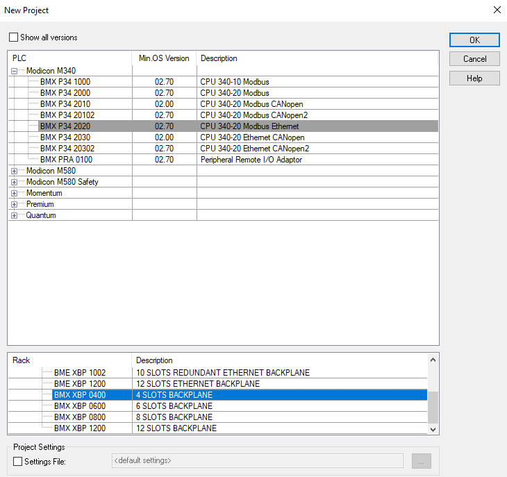
Create a new project in EcoStruxure Control Expert Small or Extra Large:
Select the processor BMXP342020 under Modicon M340, and rack BMXXBP0400:
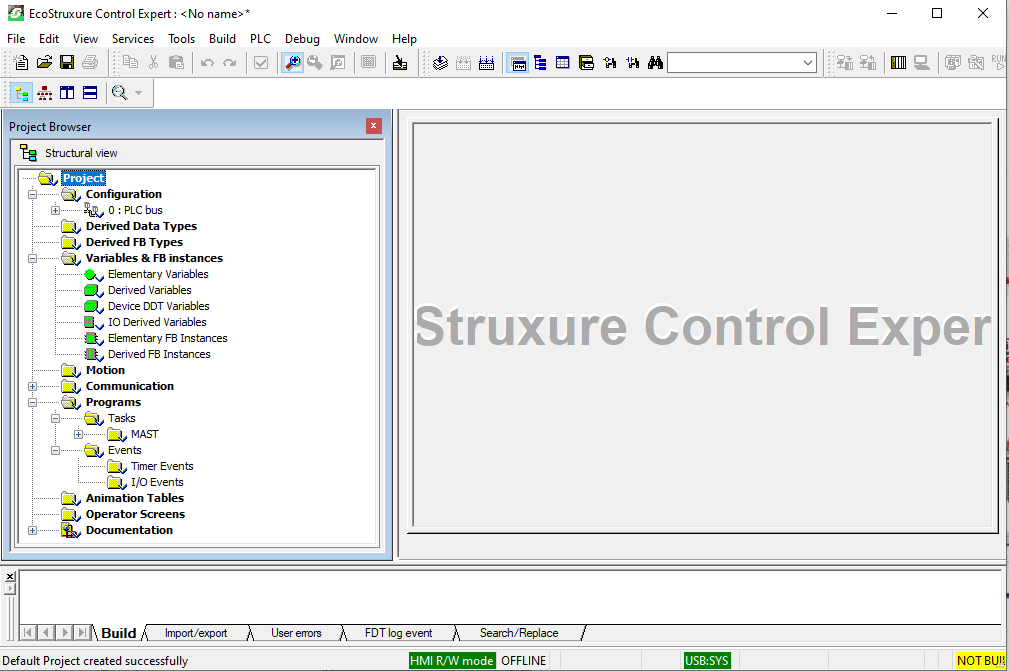
Click OK and a new project will be created:
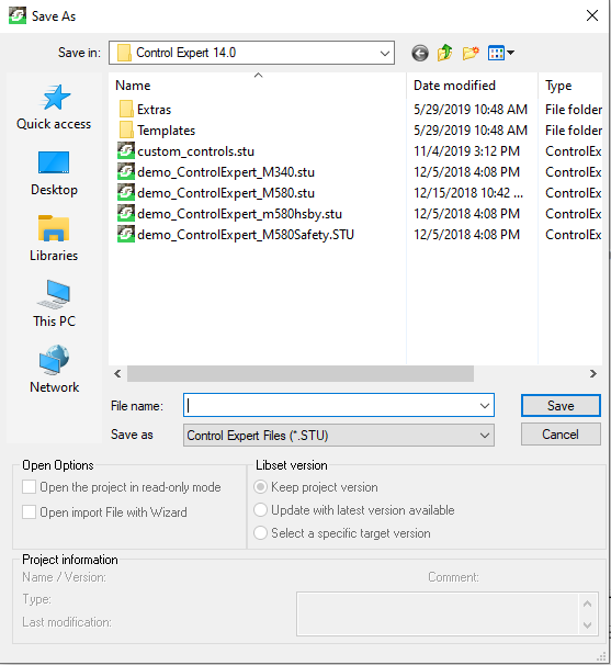
Then save your project and give it a name:


Step 2:
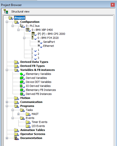
In Project Browser, navigate to Configuration and expand the tree to access Serial Port. Double Click Serial Port to modify the settings:
Image By Farhan Michael
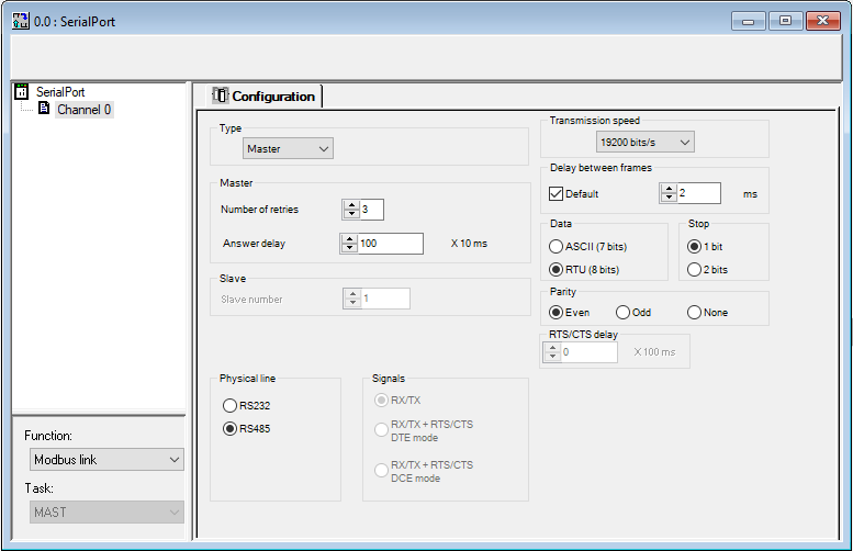
Configure the port as Modbus Master as shown below:
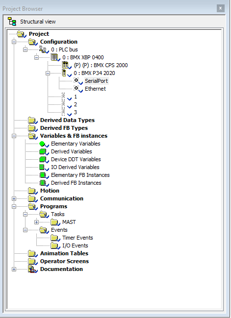
Validate your changes:
Do not forget to save your project.

Step 3
In this step, you will need to define array data structures that you can use to read and write data from drive to PLC and vice versa. You will access Variables & FB Instances in Project Browser window as shown below.

You will need to use Read_Var and Write_Var instructions in the program to exchange data between PLC and drive.
These instructions require slave address defined as input to these instructions. ADDM function is used to convert a character string into an address that can be used by the communication functions such as Read_Var and Write_Var.
You will use ADDM function to set ATV320 as slave device at address 1 and can connect upto 32 slave devices if needed. This tutorial refers to only one slave device.
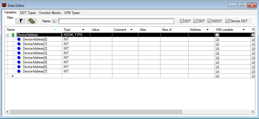
Define a DeviceAddress array of type ADDM_TYPE as shown below:

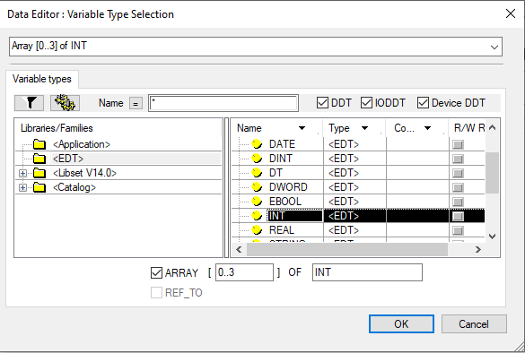
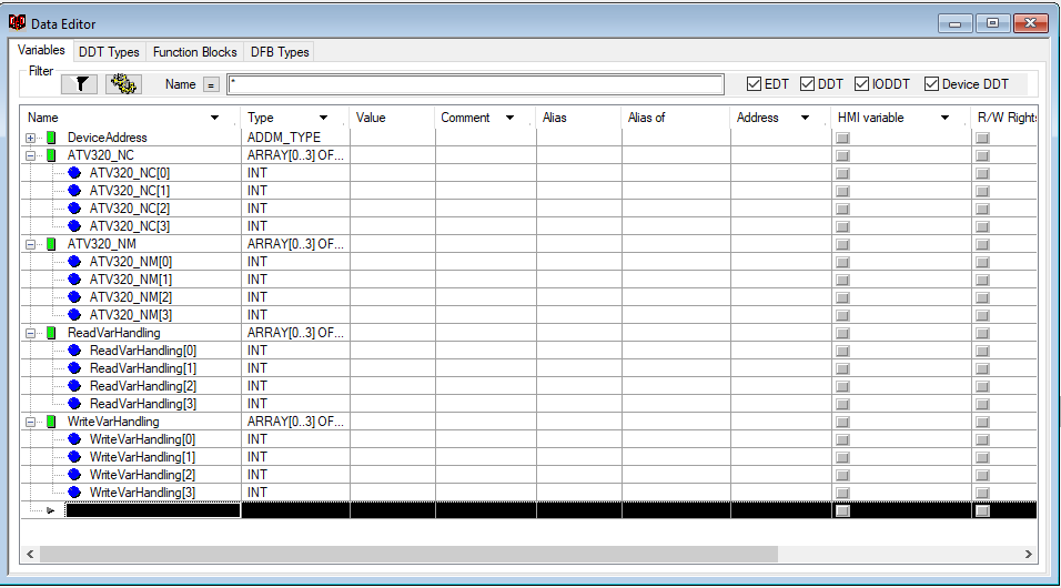
Then create four more arrays of INT(Integer) data type of size 4:


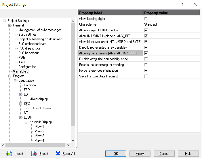
Since you have created arrays with dynamic addresses so you will need to enable dynamic array addressing in Project Settings.
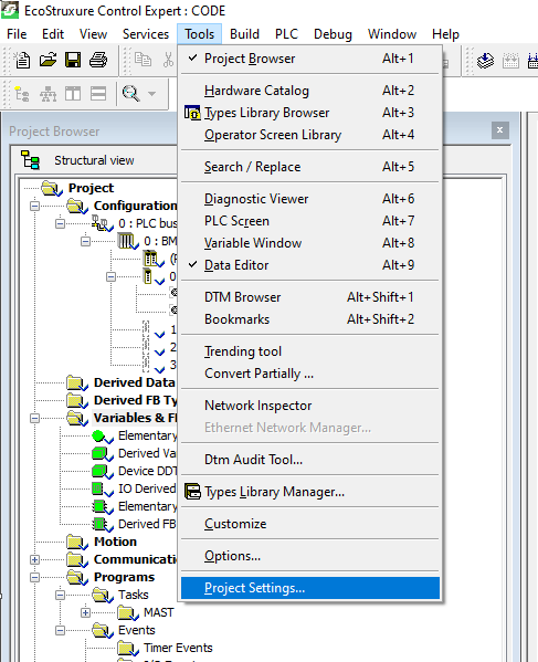
To achieve this, you will have to go on menu bar and select Project Settings under Tools:

Select Variables and enable Directly represented array variables as well as Allow Dynamic arrays (ANY_ARRAY_XXX):

Click Apply and then OK.

Step 4
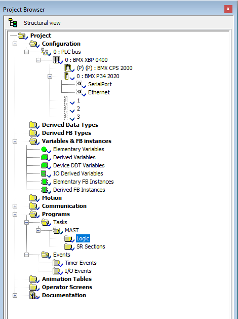
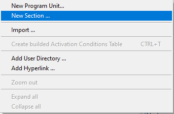
In this step you will need to write the program in Mast section. Right click on Logic and select New Section.


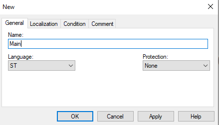
A new section window will open up. You will need to give it a name like Main and select programming language. In this tutorial, I have selected ST (Structured Text).

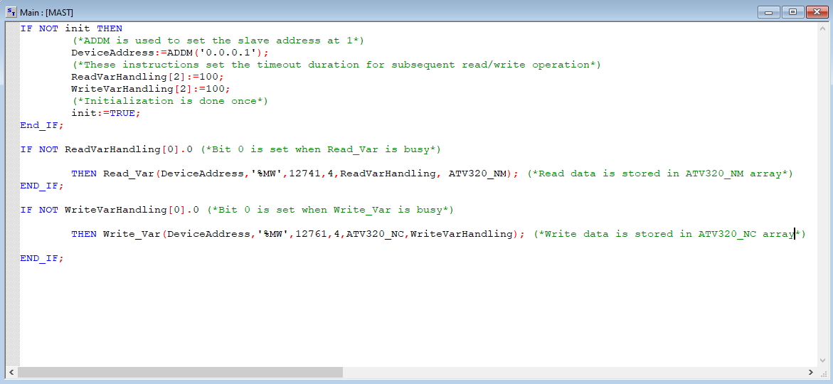
Type in the following code in Main section.

Save your project.
In the above code, the application manages two requests: A read request of four words starting at Modbus address 12741 (31C5 hex,) and a write request of four words starting at Modbus address 12761 (31D9 hex).
First two read words are mapped to Status Word and Output Speed of the drive.
Similarly, first two write words are mapped to command word and speed reference of the drive.

Step 5
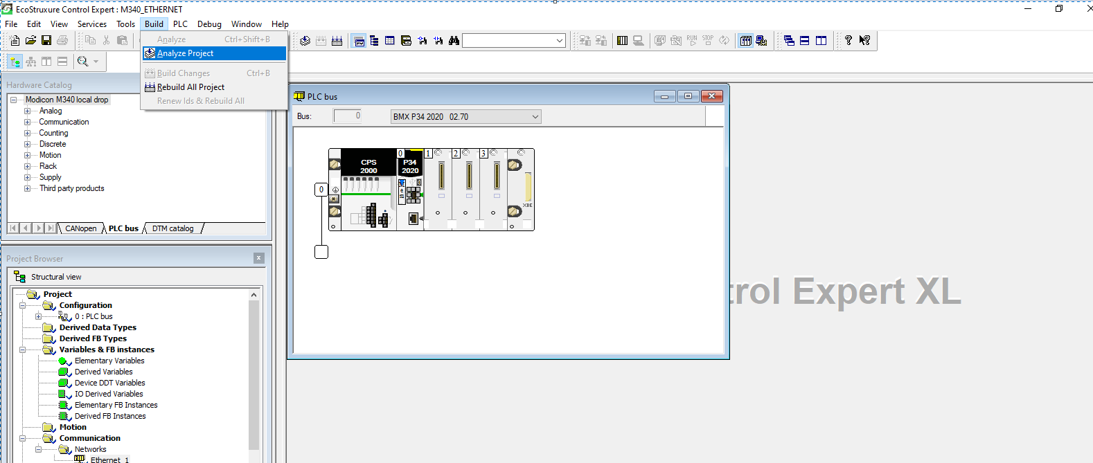
From menu bar, select Build and choose Analyze Project to compile your project:

The project should build with no errors.
Next you will need to download program to the PLC. Select Connect under PLC on menu bar provided that you have connected PC and PLC via Schneider USB programming cable:

I have used Simulator running at 127.0.0.1 for this tutorial. You will see status as DIFFERENT and NO CONF since no configuration have been transferred to PLC and applications in PC and PLC are different.
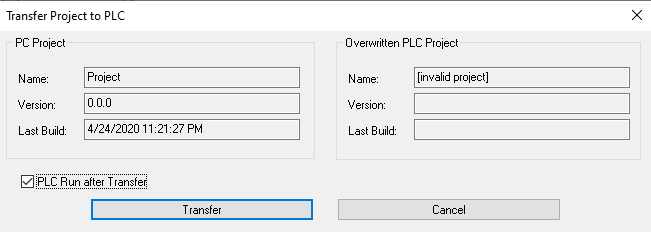
Select Transfer Project to PLC or use CTRL+L on keyboard to load application into PLC:

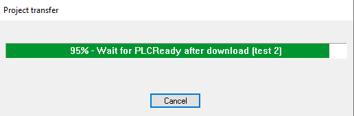
The application is now loaded, and PLC is in RUN mode.

Connect the PLC and drive via patch cord.

Step 6
In this step you will need to configure the ATV320 drive so it can communicate over Modbus via its communication scanner.
It is recommended to factory reset your drive before you do any configurations.
Factory Reset
To perform a factory reset from power up, enter the following on the dial:
  1. Scroll down to CONF menu and enter.
  2. Scroll down to FCS- and enter.
  3. Scroll down to FRY- and enter.
  4. Select All so that ” mark is at top instead of bottom.
  5. Now go to GFS parameter.
  6. Set it to yes and hold for 2 seconds until it goes back to GFS when you let go.
Command Settings
To control the drive with Modbus Master, you will have to select Modbus as active command channel. This can be achieved by selecting the following options from the face of the drive.
Enter on dial:
  1. CONF>FULL>CTL->Fr1> [MODBUS] MdB
  2. Set the command channel to Modbus
  3. CONF>FULL>CTL->Cd1> [Modbus] MdB
  4. You will also need to set the channel profile to I/O Profile.
  5. CONF>FULL>CHCF> [I/O Profile] IO
Communication Settings
Select the following
  1. CONF>FULL>COMM->Md1>Add>1
  2. CONF>FULL>COMM> [Modbus Baud Rate] tbr > [19.2 kbps] 192
  3. CONF>FULL>COMM> [Modbus Format] tFo >[8-E-1] 8 E 1
  4. CONF>FULL>COMM> [Modbus time out] tto > 10s
Power cycle the drive to make changes effective.
Share:

ONLINE SHOP : PRODUK AUTOMATION

ONLINE SHOP : PRODUK AUTOMATION
________CITAYAM AUTOMATION________

Followers

View

Translate