Tuesday, November 24, 2020

How to control an Altivar ATV320 VFD over Modbus with a Modicon M340 PLC

    In this article I would like to show you how to control an ATV320 variable frequency drive using Modbus serial port on M340 PLC. Before we begin, following is the list of items you need :
  1. PC with EcoStruxure Control Expert Small Software installed
  2. Schneider Electric Modicon (BMXP342020) PLC
  3. Schneider Electric Altivar ATV320 (ATV320U07M3C)
  4. SoMove, Drive Commissioning Software
  5. Schneider Electric Drive Programming Cable (TCSMCNAM3M002P)
  6. Schneider Electric USB Programming Cable (TCSXCNAMUM3P)
    Before we look into the programming of ATV320 and M340 PLC, let us take a look at Modicon M340 PLC and Altivar ATV320 variable frequency drive.

A. M340 PLC
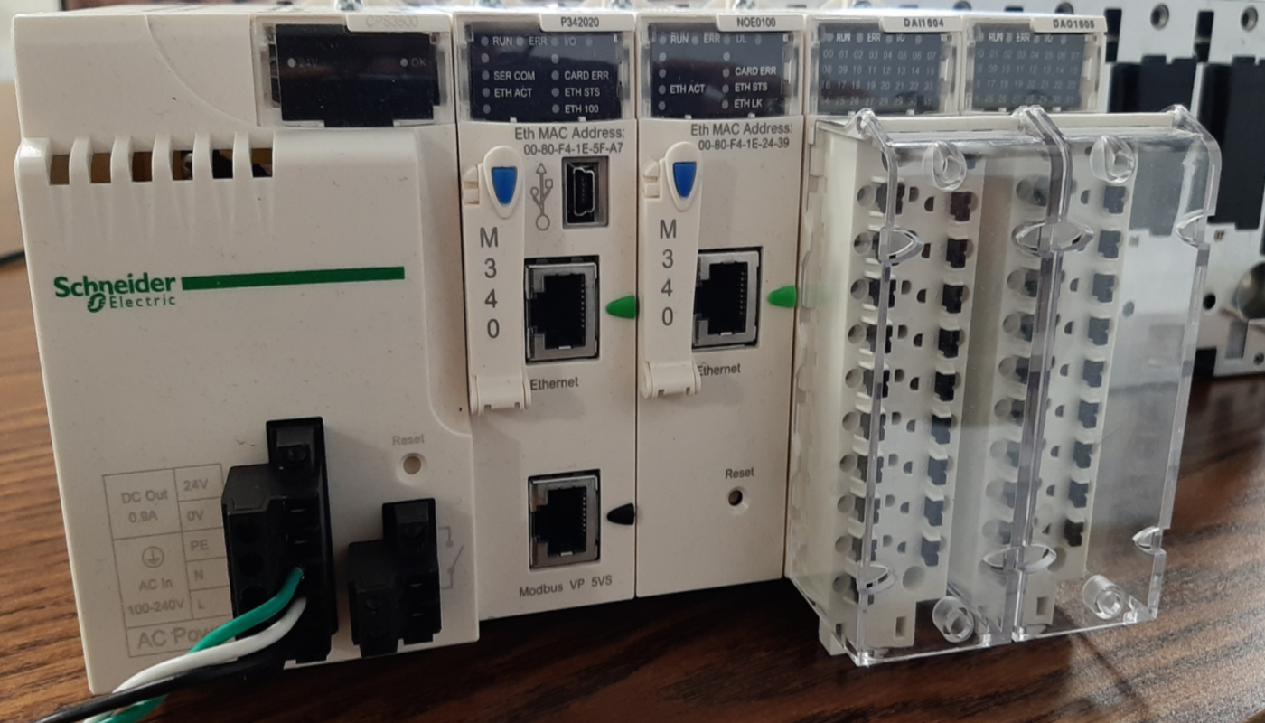
    Modicon M340 is one of the Programmable Automation controllers (PAC) that Schneider Electric offers. It is built as all in one controller approach and can cater to wide range of demanding automation applications.
    It comes built in with USB port for programming and HMI (Human Machine Interface) and two additional ports as required: Ethernet, Modbus, CANOpen. EcoStruxure Control Expert software is used for programming and commissioning of this controller.
B. Altivar ATV320
    This family of Altivar drives is specifically designed to cater to Original Equipment Manufacturers (OEM) applications with horsepower range from 0.25hp to 20hp.
It is available in two form factors, book and compact. It comes with embedded safety such as STO (Safe Torque Off) and can support different communications such as Ethernet/IP and Profinet using option cards.

Step by Step Procedure to Integrate ATV320 drive with Modicon M340 PLC

Step 1:
Create a new project in EcoStruxure Control Expert Small or Extra Large:
Select the processor BMXP342020 under Modicon M340, and rack BMXXBP0400:
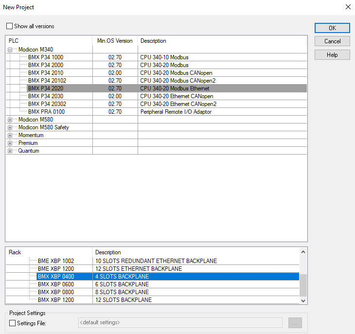
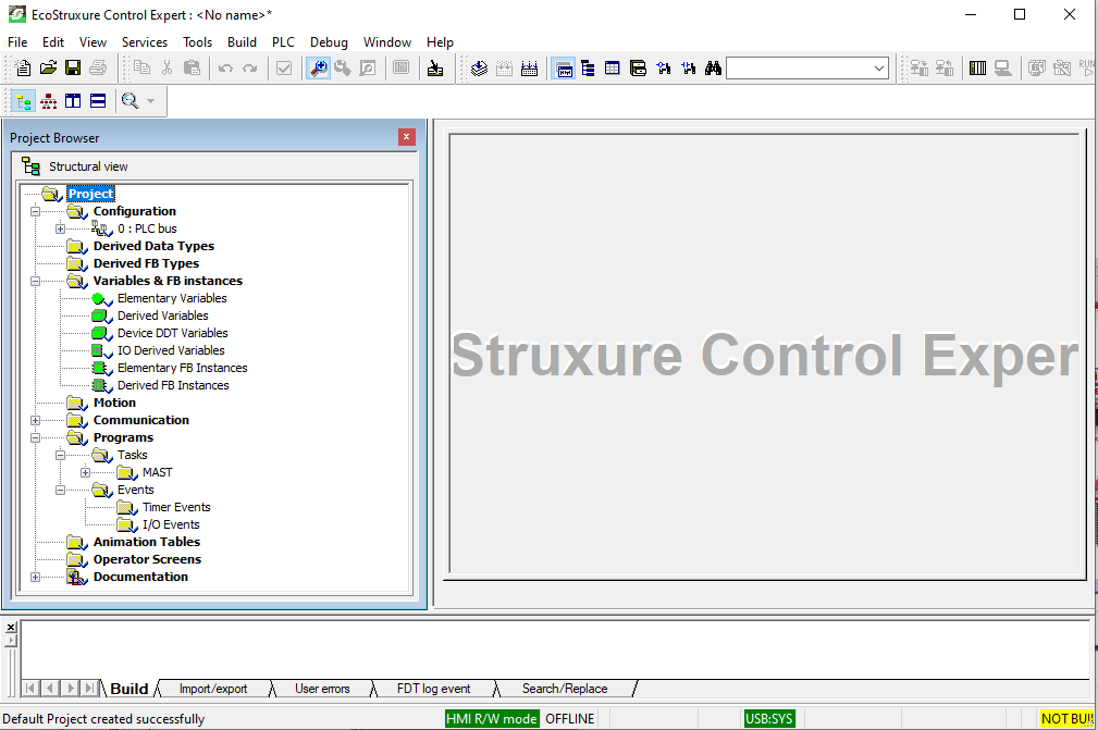
Click OK and a new project will be created:
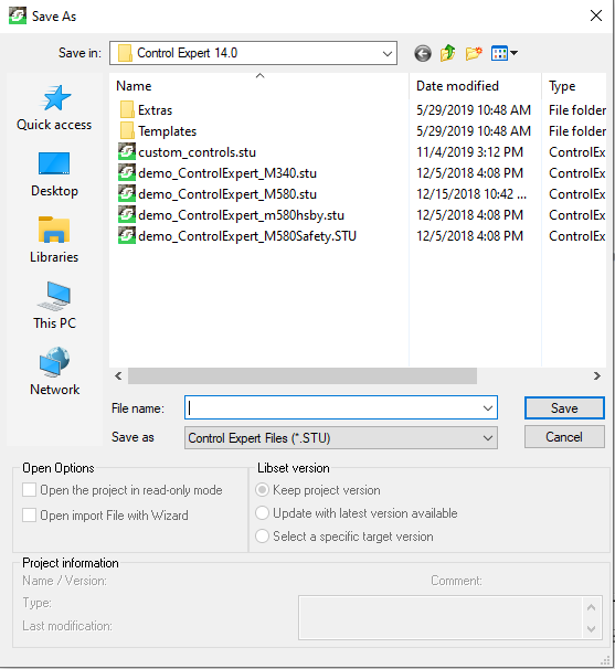
Then save your project and give it a name:


Step 2:
In Project Browser, navigate to Configuration and expand the tree to access Serial Port. Double Click Serial Port to modify the settings:
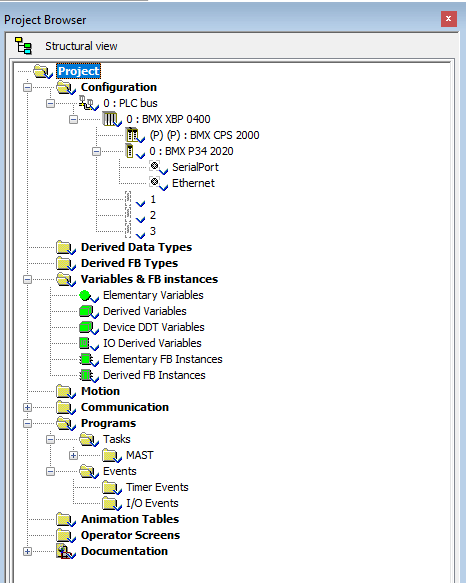
Image By Farhan Michael
Configure the port as Modbus Master as shown below:
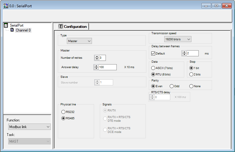
Validate your changes:
Do not forget to save your project.

Step 3
In this step, you will need to define array data structures that you can use to read and write data from drive to PLC and vice versa. You will access Variables & FB Instances in Project Browser window as shown below.
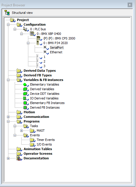
You will need to use Read_Var and Write_Var instructions in the program to exchange data between PLC and drive.
These instructions require slave address defined as input to these instructions. ADDM function is used to convert a character string into an address that can be used by the communication functions such as Read_Var and Write_Var.
You will use ADDM function to set ATV320 as slave device at address 1 and can connect upto 32 slave devices if needed. This tutorial refers to only one slave device.
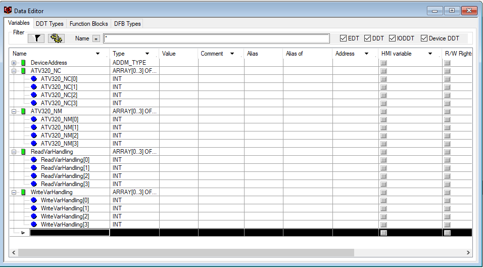
Define a DeviceAddress array of type ADDM_TYPE as shown below:
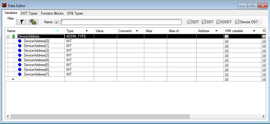
Then create four more arrays of INT(Integer) data type of size 4:
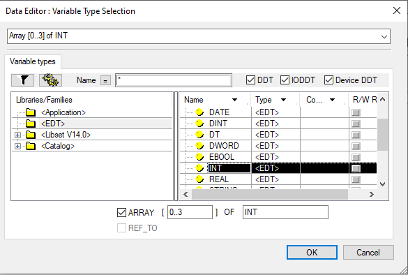

Since you have created arrays with dynamic addresses so you will need to enable dynamic array addressing in Project Settings.
To achieve this, you will have to go on menu bar and select Project Settings under Tools:
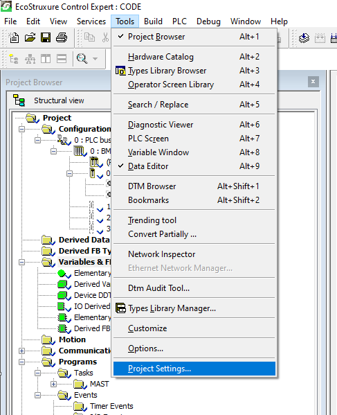
Select Variables and enable Directly represented array variables as well as Allow Dynamic arrays (ANY_ARRAY_XXX):
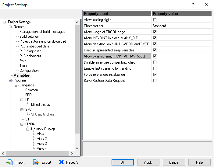
Click Apply and then OK.

Step 4
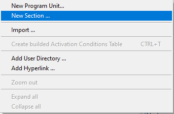
In this step you will need to write the program in Mast section. Right click on Logic and select New Section.
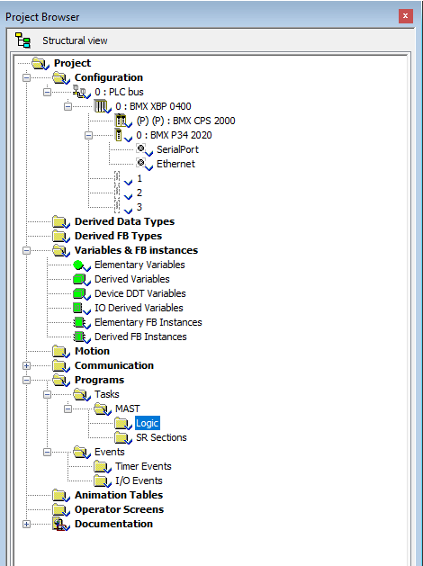

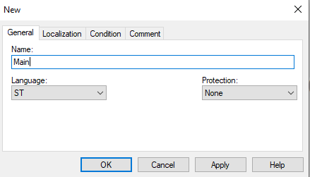
A new section window will open up. You will need to give it a name like Main and select programming language. In this tutorial, I have selected ST (Structured Text).
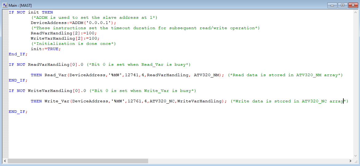
Type in the following code in Main section.
Save your project.
In the above code, the application manages two requests: A read request of four words starting at Modbus address 12741 (31C5 hex,) and a write request of four words starting at Modbus address 12761 (31D9 hex).
First two read words are mapped to Status Word and Output Speed of the drive.
Similarly, first two write words are mapped to command word and speed reference of the drive.

Step 5
From menu bar, select Build and choose Analyze Project to compile your project:
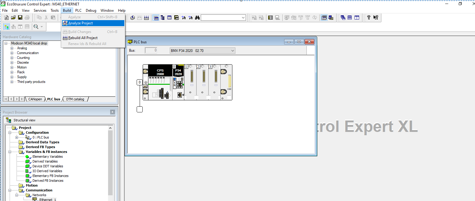
The project should build with no errors.
Next you will need to download program to the PLC. Select Connect under PLC on menu bar provided that you have connected PC and PLC via Schneider USB programming cable:

I have used Simulator running at 127.0.0.1 for this tutorial. You will see status as DIFFERENT and NO CONF since no configuration have been transferred to PLC and applications in PC and PLC are different.
Select Transfer Project to PLC or use CTRL+L on keyboard to load application into PLC:
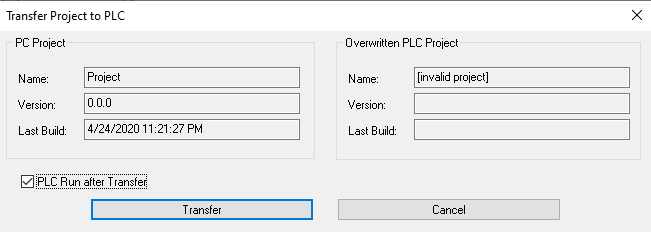
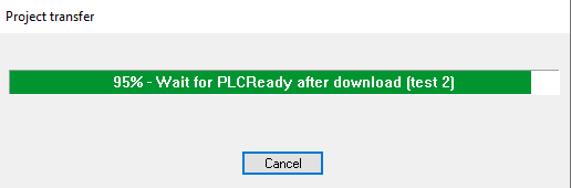
The application is now loaded, and PLC is in RUN mode.

Connect the PLC and drive via patch cord.

Step 6
In this step you will need to configure the ATV320 drive so it can communicate over Modbus via its communication scanner.
It is recommended to factory reset your drive before you do any configurations.
Factory Reset
To perform a factory reset from power up, enter the following on the dial:
  1. Scroll down to CONF menu and enter.
  2. Scroll down to FCS- and enter.
  3. Scroll down to FRY- and enter.
  4. Select All so that ” mark is at top instead of bottom.
  5. Now go to GFS parameter.
  6. Set it to yes and hold for 2 seconds until it goes back to GFS when you let go.
Command Settings
To control the drive with Modbus Master, you will have to select Modbus as active command channel. This can be achieved by selecting the following options from the face of the drive.
Enter on dial:
  1. CONF>FULL>CTL->Fr1> [MODBUS] MdB
  2. Set the command channel to Modbus
  3. CONF>FULL>CTL->Cd1> [Modbus] MdB
  4. You will also need to set the channel profile to I/O Profile.
  5. CONF>FULL>CHCF> [I/O Profile] IO
Communication Settings
Select the following
  1. CONF>FULL>COMM->Md1>Add>1
  2. CONF>FULL>COMM> [Modbus Baud Rate] tbr > [19.2 kbps] 192
  3. CONF>FULL>COMM> [Modbus Format] tFo >[8-E-1] 8 E 1
  4. CONF>FULL>COMM> [Modbus time out] tto > 10s
Power cycle the drive to make changes effective.
Share:

Monday, November 23, 2020

The Industrial Internet of Things (IIoT)

What is IIoT?

    IIoT Definition: IIoT, smart manufacturing, digital factory, digital plant, connected industry, Industry 4.0, intuitive industries. No matter what you call this disruptive transformation of industry, it offers — through the power of sensors, secure connectivity, and an IIoT platform — improved productivity, efficiency, sustainability, and cybersecurity across both new and legacy manufacturing facilities.

Six things you need to know about IIoT

1. Why is the IIoT evolution accelerating?

    Four reasons driving IIoT investment

    Manufacturing presents one of the largest opportunities for seizing the tangible return on IIoT investment:

a. Better management

Managing a large number of assets involved in manufacturing, including fleets of highly specialized machines.

b. Time savings

Reducing the time it takes to make products, in the face of ever-changing market and consumer variables.

c. Cost reduction

Improving internal business efficiency, while also helping to reduce operational costs and maintenance costs

d. Customer experience

Solving customer pain points and transforming the customer experience, while also helping customers contain costs


2. What are IIoT's business benefits?

    Three reasons to seize IIoT's value: 

    In manufacturing, 63% of businesses see IoT as a “strategic” path for competing more effectively with products and services, enabling companies to:

a. Improve the business

    IoT can drive both energy and operational efficiencies within manufacturing organizations, boosting quality, throughput, yield, and constraint management.

b. Make big data meaningful

    IIoT is the foundation for enabling advanced analytics that will drive real-time decisions, both on the spot and across the organization.

c. Thrive in the digital economy

    IIoT is a key enabler of innovation, digital transformation, and the development of new digital, customer-centric business models.


3. What are some successful IIoT examples?


Examples of IIoT with EcoStruxure 

    In manufacturing, 63% of businesses see IoT as a “strategic” path for competing as an intuitive industry. Both manufacturing companies and OEMs illustrate the competitive advantage of regarding IIoT adoption as a key business strategy instead of a technology issue. The following EcoStruxure customers demonstrate the successful digital transformation of their business.


4. What's a common IIoT project funding approach?

    Three recommendations for successful IIoT project funding 

    Understanding who initiates IoT projects — and, perhaps more importantly, who funds IoT projects — helps identify how to launch an ultimately successful project in your company. Here are some recommendations:

a. Strategically budget projects

Increasingly, the majority of IIoT projects are budgeted, indicating that they are indeed part of the strategic planning process.

b. Scale your long-term investments

It is critical to consider as well the longer-term budget requirements of managing, maintaining, and expanding to include other endpoints and connected "things” over time.

c. Align IT and the lines of business

Creating the link between the business needs and IT requirements early in the process will alleviate issues in the long term.

5. How can you launch your IIoT Partner Ecosystem?

Top 5 questions to ask a potential IIoT vendor 

a. What makes this IIoT offer worth the investment from a business standpoint?

b. Is your solution interoperable across systems (even other vendors’ components)?

c. Which cybersecurity certifications and measures are in place with your solution?

d. Do you have a comprehensive partner ecosystem that can help with installation and integration?

e. Which digital services do you have that go along with this offer?

Accelerating IIoT adoption with our extended enterprise co-innovation partners

Thriving in today's digital economy requires speed, expanded expertise, and agility. Digital alliance partners complement Schneider Electric's technology and knowledge to create solutions that solve specific market challenges, enabling customers to scale and accelerate their digital transformation.


6. How do you select an IIoT Vendor?

What makes a good IIoT partner? 

As manufacturers are making investments to digitally transform their business, there are several key criteria they are using to select a vendor(s) to support their IIoT projects. According to recent research of manufacturers that have deployed IIoT offers and solutions, the key elements to look for in your vendors include the following

a. Proven track record

Focusing on the key benefits of an IIoT investment such as internal improvements and cost containment will help raise the bar of the return on investment in IIoT, in turn, persuading C-suite management to invest.

b. Robust partner

Any IIoT solution will need technology elements from a variety of vendors; however, those vendors that can pull together a holistic IIoT solution through strategic technology partnerships should be strongly considered.

c. Industry-specific

Vendors who have knowledge of the manufacturing sector and familiarity with your company’s pain points in specific business processes will help shorten the time to create an IIoT project concept to trial.

d. Interoperable approach to solutions

Vendors who employ an “open” approach to their technology offerings provide a flexible and future-proofed option for longer-term IIoT requirements. For a heterogeneous equipment environment, machine-to-machine communication is essential to driving efficiencies.


Share:

Thursday, November 19, 2020

Soft starter Altistart 48

Altistart 48

Soft Starters for heavy duty industry & pump from 4 to 900kW. ATS48 offers reliable, robust and high performance Soft Starters for your motors with unique Torque Control Systems (TCS).

A. Features

  • 230... 415 V / 208... 690 V - 50/60 Hz
  • Starting and stopping of the machine by the Altistart 48 torque control system (TCS patent: Torque Control System)
  • Thermal protection of the motor
  • Protection of the machine: underload and overload with adjustable threshold and times, locked rotor, rotation direction control
  • Factory set for immediate start-up
  • Simplified customisation of settings using built-in display or the PowerSuite software
  • Through connection
  • Control of starter bypass contactor to prevent heat dissipation
  • Dual configuration (2 motors)
  • Numerous configurable inputs/outputs
  • Cascaded starting and deceleration of a number of motors
  • Modbus Integrated, FIPIO, PROFIBUS DP, DeviceNet, Ethernet

B. Benefits

Altistart 48 delivers:

  • High performance with its Torque Control System (TCS) for controlled starting and deceleration
  • Easy integration in enclosures and control systems
  • Continual improvement of your machine operation by reducing mechanical or hydraulic stress and limiting energy loss and temperature rise, plus more

Taming energy

    Altistart 48 offers you the benefits of its patented Torque Control System (TCS). Ready for immediate start-up, with simplified wiring and extended communication functions, it can be integrated at the heart of your applications in complete simplicity.

C. Applications

  • Pumps
  • Fans and high inertia machines
  • Compressors
  • Conveyors 
D. Getting started with Altistart 48

1. Wire the soft starter
  • Wire the soft starter to the ground.
  • Wire the motor (2/T1 - 4/T2 - 6/T3), ensuring that its coupling corresponds to the supply mains voltage
  • Wire the supply mains (1/L1 - 3/L2 - 5/L3)
  • Wire the control (CL1 - CL2)
  • Caution: note the supply voltage according to the range. (230 – 415V : Range Q,  208 – 690V : Range Y)
Start                            Delta
  • Installation of fast-acting fuses for type 2 coordination (conforming to IEC 60 947-4-2)
  • Assignment of relay R1: isolating relay (r1I). Beware of the operating limits of the contact, for example when connecting to high rating contactors.
  • Insert a transformer if the supply voltage is different to that permitted by the ATS 48 control.

2. Power up the control part
    Power up without the power part and without giving the run command.
  • Check that S2 is open.
  • Switch on: Q1, then Q3, then Q4.
  • The starter displays: nLP (to indicate that the power is switched off)
3. Adjust settings
  • Adjust In nominal motor current (See Nominal Motor Current on Motor Nameplate)
  • Set R1 to r1I

4. Power up the power part and start the motor
  • Switch on Q5.
  • The soft starter displays: rdy (to indicate that the soft starter is powered-up and ready).
  • Close S2.
5. Factory settings
    The Altistart 48 is factory-set for the most common operating conditions. If the factory configuration is not suitable for your application, refer to User manual (1494409) on www.schneider-electric.com. Here is the list of writable parameters in an “easy start up” mode

  • Management of the displayed value "XXX" is given in the table below. 
  • Menu St2. is only visible if the "second set of motor parameters" function is configu
6. Display of soft starter status
    The displayed value "XXX" follows the following rules:
    When current limiting is applied to the soft starter, the displayed value "XXX" flashes. It is still possible to modify the parameters even if an error occurs on the soft starter.

7. Troubleshooting
  • The FrF detection is done only at the first power ON of the power part supply.
  • For next Power ON of the power part supply, bad frequency will also generate a desynchronization error PHF. 
  • Refer to the user manual (1494409) for comprehensive troubleshooting information.


What are the precautions to be taken care while using ATS22/ATS48 soft starter for long motor cable of 500 meter? Is there any parameter setting required for long cable?

There is no special parameter setting in soft starter depending upon cable length. But the customer can take care of some of points during its installation for avoid voltage drop and leakage current. 
  • The motor cable length shall not be problem, if the motor cable is well sized and voltage drop is not causing inadequate current rise.
  • The voltage drop is proportional to the length of motor cable. Hence you should get confirmation from motor manufacturer that, "whether the motor will capable of driving the load with out any problem with the drop in voltage of 5  to 10%".
  • Please ensure the motor insulation is Class F and above to reduce the leakage current and improved thermal capability.
  • It is recommended to over size the soft starter rating adequately(at least 10 to 20% extra de-rating to other de-rating factors). 
  • It is recommended to use the soft starter with end of bypass contactor. So that the internal losses due to thyristor switching is avoided during normal running.
  • Voltage drop during starting can be compensated by setting tq0 [initial voltage] to higher value (may be 30 to 50%)


Share:

Monday, November 09, 2020

Different Types of M580 I/O

    In Automation architecture, the heart of a system is a PAC. Information coming from the field (sensors, push buttons, etc.) and commands sent to the devices (motor control, variable speed drive references, etc.) are often linked to the PAC via digital or analogue inputs and outputs. These inputs and outputs are physically connected through wiring between field devices and input and output modules.

These modules can be located in different positions: Locally, Remotely, or Distributed.

Local I/O

    Local I/O consists of input and output modules that are located in the local rack of the PAC. The internal backplane is used as a medium of communication. This structure can achieve very high performances in terms of response time.


I/O modules located on Extension racks are also considered as Local I/O.

Distributed I/O

    To achieve greater distances and flexibility, Distributed I/O ia a reasonable option. Distributed I/O consists of input and output modules but also specific modules (to better integrate devices) located on an island which communicate with the PAC over a fieldbus or network.


Due to the fieldbus communication over the network, Distributed I/O has a limitation in terms of performance depending on the medium used between them and the PAC.

Remote I/O

    Remote I/O consists of input and output modules located separate to the Local PAC and Local I/O rack. Remote I/O uses specific / proprietary communications which allows for similar performance to Local I/O because data acquisition from them is asynchronous to the CPU scan. Remote I/O eliminates expensive point-to-point wires by networking just a few (or thousands) of process signals onto one digital communication link.


One of the main advantages of Remote I/O is that the entire configuration is often completed using one unique software tool.

The M580 Remote I/O offer provides reliability and performance with the availability to integrate Distributed Remote I/O drops over the Ethernet network. The system uses Ethernet/IP technology based on the reliable CIP object model. The figure below shows an example of a PlantStruxure system with M580 as a global automation solution:
The M580 system uses Modicon X80 I/O modules, many of which are used in an M340 system. The system also supports several Ethernet-based eX80 I/O modules, which can be installed on both the main local rack and main remote racks. The local rack can also support an extension rack of Premium I/O modules.


Share:

ONLINE SHOP : PRODUK AUTOMATION

ONLINE SHOP : PRODUK AUTOMATION
________CITAYAM AUTOMATION________

Followers

View

Translate