Thursday, October 28, 2021

Siemens S7-300 (Ethernet:ISO over TCP/IP) Addressing


Memory Type

Range

Description

Read/Write

Data Type

I

I

0.00 - 65535.7

Input Memory

R/W

Bit

IB

0 - 65536

Byte

IW

0 - 65535

Word

ID

0 - 65535

Double Word

Q

Q

0.00 - 65535.7

Output Memory

R/W

Bit

QB

0 - 65536

Byte

QW

0 - 65535

Word

QD

0 - 65535

Double Word

M

M

0.00 - 65535.7

Internal Memory

R/W

Bit

MB

0 - 65536

Byte

MW

0 - 65535

Word

MD

0 - 65535

Double Word

DB

DBX

1.0 - 65535.65535

Data Block

Memory

R/W

Bit

DBB

Byte

DBW

Word

DBD

Double Word

* T

0 - 255

Timer Acc.

R/W

Word

* C

0 - 255

Counter Acc.


Word

* Timers and Counters only accept values up to 999 in BCD.  If you attempt to write a value greater than 999, it will only accept the lower 12 bits (least significant 3 digits).  The upper 4 bits are used for the Time Base.  Refer to Siemens documentation for a more specific breakdown of the Timer Bit pattern.

Siemens Elementary Types

C-more Tag Data Type

Siemens Memory Types

BOOL

Discrete

I/Q/M/DBX

BYTE

Signed Int 16

IB/QB/MB/DBB

WORD

IW/QW/MW/DBW

INT

DWORD

Signed Int 32

ID/QD/MD/DBD

DINT

REAL

Floating PT 32

ID/QD/MD/DBD

CHAR

Ascii String

DBB String/DBB Char

View the PLC Variables Status

To view the Status of the Variables in the PLC, once you are Online with the PLC, from the Main Menu of the SIMATIC Manager Software, click on the PLC (1) selection and select Monitor/Modify Variables (2) from the drop-down menu as shown below.

The Variables Monitoring window shown below will open.  From this window, you can enter the Variables and Monitor their states.

Data Block Addressing

Data Block Addressing syntax differs some between what is seen in the SIMATIC Software and in C-more.  To view the Data Block, double click on the specific Data Block you wish to view in the main SIMATIC Manager window.  When a specific Data Block is selected, a window like the one shown below will open.


From the figure shown above:

  1. The image above shows DB1.

  2. Inside DB1, there are Four Variables:

    • MOTOR_RPM is addressed at byte0 and is a 16 bit Integer.
    • SETPOINT_RPM is addressed at byte2 and is also a 16bit Integer.
    • START is addressed at byte 4, bit 0 and is a Boolean.
    • STOP is addressed at byte 4, bit 1 and is a BOOLEAN.

These Four Variables would be Addressed as follows in C-more:

  1. MOTOR_RPM = Memory Type:  DB.DBW  Address:  1.0

  2. SETPOINT_RPM = Memory Type:  DB.DBW  Address: 1.2

  3. START = Memory Type:  DB.DBX  Address:  1.4   Bit:  0

  4. STOP = Memory Type:  DB.DBX  Address:  1.4  Bit:  1

SIMATIC Variables Addressing Siemens Vs. C-more

SIMATIC Variable

Siemens Addressing

C-more Addressing

Memory Type

Address

Bit

MOTOR_RPM

DB1.DBW 0

DB.DBW

1.0


SETPOINT_RPM

DB1.DBW 2

DB.DBW

1.2


START

DB1.DBX 4.0

DB.DBX

1.4

0

STOP

DB1.DBX 4.1

DB.DBX

1.4

1


Note: Please note that there is a space (shown in red on the Address sample) on all the Siemens Addressing (DB1.DBW 0).

Note:
The information provided above for C-more Addressing is used for the C-more PLC Address fields shown below.


Using the Variable #3 as a sample, the Tag Name window from C-more would look as follows:

If you view these Variables in the Variable Table of the SIMATIC Manager, they look more like the C-more syntax.  To view, from the Main Menu of the SIMATIC Manager Software, click on the PLC (a) selection and select Monitor/Modify Variables (b) from the drop-down menu as shown below.

The Variable Monitor Table window shown below will open.  From this window you can Monitor the Variables shown.


Share:

Thursday, August 12, 2021

Pengukuran Vibrasi pada Motor atau Pompa

Untuk apa sih mengukur getaran/vibrasi? ini sama seperti kita mengukur tingkat kesehatan manusia, begitu juga kita harus tahu tingkat kesehatan sebuah mesin / motor listrik, salah satu nya ya dengan mengukur dan memonitor vibrasi nya.

Mesin-mesin apa yang harus dimonitor vibrasinya?
secara umum, mesin-mesin yang harus diperhatikan adalah berdasarkan tingkat kepentingan sebuah mesin tersebut antara lain :

a. Mesin yang cukup mahal, besar, dan susah diperbaiki jika terjadi kerusakan
b. Mesin yang memberikan dampak yang besar terhadap produksi sebuah pembangkit (plant)
c. Mesin yang diketahui sering kali mengalami kerusakan
d. Mesin yang sedang diukur kehandalannya
e. Mesin yang memberikan dampak keselamatan terhadap manusia maupun peralatan lain (safety)
Fig 35

Bagaimana instrument pengukuran bekerja?

Sebelum mengukur vibrasi, kita perlu tau sensor apa yang digunakan untuk mengukurnya. Kebanyakan sih yang dipakai adalah sensor accelerometer, jadi dia memproduksi sinyal kecil yang sebanding dengan akselerasi dari peralatan yang bergetar tersebut. Apa sih akselerasi pada komponen yang bergetar? maksudnya seberapa cepat perubahan velocity yang terjadi. apa sih velocity??? mbulet yaa….

Fig 36

Bagaimana mengukur nya?

Pertama, bagaimana meletakkan accelerometer nya? ingat, jika mau mengukur vibrasi di bearing maka jangan letakkan alat ukut di body… contoh seperti dibawah

Fig 37

a. Letakkan sedekat mungkin pada bearing

ini untuk menghindari distorsi signal dan kesalahan dalam pembacaan.
Fig 39

b. Pastikan alat ukurnya terpasang dengan baik

sama, efeknya akan menyebabkan kesalahan dalam pembacaan sinyal oleh alat ukurnya .
Fig 40
Fig 41

Fig 42Fig 43

c. Pastikan orientasi pengukuran tepat

Jika akan mendeteksi parallel missalignment, maka biasanya alat ukur diletakkan pada posisi radial dari bearing. Sedangkan untuk mengukur angular missalignment, alat ukur diletakkan dalam posisi sumbu axial.
Sinyal yang diproduksi oleh alat ukur akan bergantung juga dari letak dan arah, karena getaran akan bervariasi di setiap letak dan arahnya.

Fig 44

d. Lakukan pengukuran di tempat yang sama.

Dalam melakukan perawatan, predictive ataupun preventive,  maka akan sangat baik jika pengukuran rutin dilakukan pada tempat yang sama..

Fig 45

e. Jaga keselamatan mu dan juga alatmu

Fig 47
Fig 48

Fig 49

Standard

Shaft Speed (RPM)
Less than 2,000
Greater than 2,000
Mounting Drive Category Mounting Drive Category
Rigid Mounting Rigid Drive I Rigid Mounting Rigid Drive II
Flex Drive II Flex Drive III

Flexible Mounting Rigid Drive II Flexible Mounting Rigid Drive III
Flex DriveIIIFlex DriveIV


Share:

Wednesday, May 05, 2021

In the M580 CPU, why does the system word %SW51 (RTC Hour) show a different value?

In the M580 CPU, why does the system word %SW51 (RTC Hour) show a different value?
How do I extract the value of the current local time hour from an M580 PLC's Runtime Clock (RTC) in a program?

Product Line
Modicon M580

Enviroment
EcoStruxure Control Expert
Unity Pro

Cause
There is a new behaviour of %SW51 in M580 platform compared to the previous M340 generation of PLC. The local time Hour is not represented in %SW51 in the M580.

Resolution
The local time can be read using the RRTC_DT function.

The RRTC_DT function returns the date and time in DateTime Type format.

This value can then be converted to an Array of 4 INTs (in BCD Format) containing:
DateAndTime_ARRAY[1] = 16#SS00  (Seconds)
DateAndTime_ARRAY[2] = 16#HHMM (Hour and Minute)
DateAndTime_ARRAY[3] = 16#MMDD (Month and Day)
DateAndTime_ARRAY[4] = 16#YYYY (Year)

These 4 INTs are structured in the same way as %SW50 to %SW53 in the M340.

Furthermore, to extract the Local time hour using the RRTC_DT function, see the screenshot below as an example:


The value from the DT_TO_ARINT array of INT variables is originally in BCD format and must be converted from BCD to INT. Then the left-most two digits represents the local time hour, which can be extracted by dividing the BCD value by 100 (with no remainder using the DIV function).


Share:

Wednesday, April 28, 2021

Link Download EcoStruxure Control Expert V15.0


EcoStruxure Control Expert installation setup (.iso file *) is unique. License determines the package that can be launched : Control Expert S, Control Expert L, Control Expert XL and Control Expert XL with M580 Safety.Licenses for Control Expert V15 are valid for V14.1 or V14.0Control Expert software comes with a 30-day trial license that it is automatically activated during first launch of the software product. It includes the maximum set of software product features which corresponds to the Control Expert XL package with M580 Safety Add-OnThis publication allows to get a copy of EcoStruxure Control Expert V15.0 DVD.... (*)“Google Chrome or Firefox browsers are recommended to download the .iso file”

ControlExpert_V15.0-IR15C_20201016B (.iso) 2.3 gb

Share:

Wednesday, February 17, 2021

Nema Rating

NEMA is a rating system for equipment that might be exposed to liquids, rain, ice, corrosion and contaminates such as dust.

If unsure of the enclosure rating that is required of your project, please refer to the design chart below. The chart will assist in specifying which enclosure rating is appropriate for the environment and application needed.

For in depth information on the different Nema ratings we offer, please continue reading to the list below.

Type 1: General purpose enclosures constructed for indoor use. Protects against dust, light, and indirect splashing but is not dust-tight. Primarily prevents incidental contact with the enclosure equipment. We adhere to NEMA standards to provide you a quality enclosure for most basic applications.

Type 3R: Intended for outdoor use. Provides a degree of protection against falling rain and ice formation. Constructed (with knockouts on the sides and bottom) to prevent beating rain from interfering with the successful operation of the apparatus or result in wetting of live parts and wiring within the enclosure under specified conditions. Please be aware that these are not rain-tight, which means exposure to beating rain could result in water entering a Type 3R enclosure under certain conditions; nor are they water-tight, which means moisture could enter a Type 3R enclosure when subjected to a stream of water under certain conditions. This style of enclosure does not have a gasketed sealing surface. Nema Enclosures manufactures NEMA 3R enclosures for housing power distribution, lighting contractors, switch gear, and other electrical components that need to be protected in an outdoor environment. Our adherence to UL 508A standards will give you a quality weatherproof enclosure resistant to rain, ice, and snow

Type 4: Weather tight (weatherproof) enclosures. Constructed for either indoor or outdoor use to provide a degree of protection against falling dirt, rain, sleet, snow, windblown dust, splashing water, and hose-directed water. Will be undamaged by the external formation of ice on the enclosure. NEMA 4X is used when protection from the worst environments is required. Our NEMA 4 enclosures come in powder coated carbon steel and are available in a variety of types, such as wall-mounted, free-standing and JIC. Nema Enclosures strictly adheres to the exacting NEMA standards in order to provide you a quality electrical enclosure at competitive price.

Type 4X: Same as Type 4 except constructed from corrosion-resistant material. Corrosion-resistant as defined by industry standards is: Constructed to provide a degree of protection against exposure to corrosive agents such as salt spray. Nema Enclosures produces these enclosures in 5052-H32 aluminum, 304/304L stainless steel, or 316/316L stainless steel and they are available in a number of styles for your demanding applications.

Stainless steel is the strongest of the corrosion resistant materials. It exhibits many of the same resistances attributed to fiberglass materials as well as resistance to highly polar solvents such as acetone and MEK.

316 grade stainless steel is the strongest of the corrosion resistant materials that provide improved resistance to salt, some acids, and high temperature. 316 grade is a strongly recommended choice for marine environments which are within 5 miles of salt water or otherwise subject to salt spray. Note that 316 grade resistance to sulfates and chlorine is less than that provided by 304 grade.

Cautionary aesthetic note: Stainless steel of any type is not “stain-free”, and while it offers a high degree of performance, under certain environmental conditions it remains susceptible to rust deposits on the surface. These deposits are often created by contamination resulting from rain or marine environments. Periodic cleaning of the surfaces of stainless steel enclosures with a neutral solution is recommended to avoid “tea staining” Regular washing with clean, fresh water or even rain water has a significant effect on reducing the incidence of tea staining.

Type 12: Constructed (without knockouts) for indoor use to provide a degree of protection to personnel against access to hazardous parts. Provides a degree of protection of the equipment inside the enclosure against ingress of solid foreign objects (falling dirt and circulating dust, lint, fibers, and fyings). Also provides a degree of protection with respect to harmful effects on the equipment due to the ingress of water (dripping and light splashing). Gasketed doors seal the enclosure’s contents from airborne contaminants and non-pressurized water and oil. Nema Enclosures produce NEMA 12 enclosures which are intended mainly for indoor industrial, manufacturing, and machining applications. We produce a number of enclosure types in aluminum, carbon steel and stainless steel delivered quickly at competitive prices. 


Share:

PROFIBUS Remote Master

 Description:

The version V1.3 fixes some installation and quality issues with new releases of:· PRM function block library: V1.1.0· PRM gateway DTM: V1.3.0.0This version V1.3 is compatible and has been fully tested with Unity Pro V11.1 version. The DTMs being upward compatible, it is possible that this version is also compatible with previous Unity Pro V8.1, V10 or V11. Anyway, it is highly recommended to install the latest Unity versions: all the Unity Hot fixes are also available on www.schneider-electric.com. Note that the Unity Hot fixes are not cumulative and have to be all installed separately.

Product Ranges:

EcoStruxure Control Expert (Unity Pro), Profibus DP Fieldbus


Files for Download

PRM_V1.3_20160908 (.iso)

Share:

Wednesday, November 25, 2020

CANopen – The standardized embedded network

    CANopen is a CAN-based communication system. It comprises higher-layer protocols and profile specifications. CANopen has been developed as a standardized embedded network with highly flexible configuration capabilities. It was designed originally for motion-oriented machine control systems, such as handling systems. Today it is used in various application fields, such as medical equipment, off-road vehicles, maritime electronics, railway applications, or building automation.

    CANopen unburdens the developer from dealing with CAN hardware-specific details such as bit timing and acceptance filtering. It provides standardized communication objects (COB) for time-critical processes, configuration as well as network management data.

"Plug and play" with CANopen

    Standardized CANopen device and application profiles simplify the task of integrating a CANopen system. Off-the-shelf devices, tools, and protocol stacks are widely available at reasonable prices. For system designers, it is very important to reuse application software. This requires not only communication compatibility, but also interoperability and interchangeability of devices. CANopen device, interface, and application profiles enable device manufacturers to provide their products with standardized interfaces to achieve CANopen devices with "plug and play" capability in CANopen networks. Nevertheless, CANopen allows implementing manufacturer-specific functionalites.

CANopen at a glance

CANopen provides several communication objects, which enable device designers to implement desired network behavior into a device. With these communication objects, device designers can offer devices that can communicate process data, indicate device-internal error conditions or influence and control the network behavior. In their products, device designers may also support CANopen functions that enable the devices to participate in point-to-point communication coherences in the network. As CANopen defines the internal device structure, the system designer knows exactly how to access a CANopen device and how to adjust the intended device behavior.

CANopen lower layers

CANopen is based on a data link layer according to ISO 11898-1. The CANopen bit timing is specified in CiA 301 and allows the adjustment of data rates from 10 kbit/s to 1000 kbit/s. Although all specified CAN-ID addressing schemata are based on the 11-bit CAN-ID, CANopen supports the 29-bit CAN-ID as well. CANopen assumes a physical layer according to ISO 11898-2. Nevertheless, CANopen does not exclude other physical layer options.

Further information on the CANopen lower layers is available here.

Internal device architecture

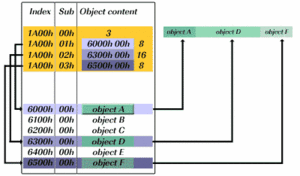
A CANopen device consists of three logical parts. The CANopen protocol stack handles the communication via the CAN network. The application software provides the internal control functionality as well as the interface to the process hardware interfaces. The CANopen object dictionary interfaces the protocol as well as the application software. It contains references (indices) for all used data types and stores all communication and application parameters.  

The CANopen object dictionary is most important for CANopen device configuration and diagnostics. As device-internal reference, a 16-bit index which is given as 4-digit hexadecimal value, is used. The index range 1000h to 1FFFh provides references to all parameters that determine the CANopen communication behavior of the CANopen device. The index range 2000h to 9FFFh provides the references to all application-related parameters. CANopen distinguishes between proprietary parameters (index range 2000h to 5FFFh) and standardized parameters (index range 6000h to 9FFFh).

Further information on CANopen internal device architecture is available here.

CANopen protocols

A CANopen protocol stack implements several CANopen COBs that are communicated with one of the CANopen bit-rates. The CANopen communication objects enable system designers to transfer control information, to react to certain error conditions or to influence and control the network behavior. The capability of CANopen devices can be evaluated by checking the existence of the related CANopen object dictionary entries that describe the communication behavior.


The CANopen protocols comprise:

  • SDO Protocol
  • PDO Protocol
  • NMT Protocol
  • Special Function Protocols
  • Error Control Protocol

A. Service data object (SDO)

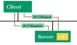
Service data objects (SDOs) enable access to all entries of a CANopen object dictionary. One SDO consists of two CAN data frames with different CAN-Identifiers. This is a confirmed communication service. With an SDO, a peer-to-peer client-server communication between two CANopen devices can be established on the broadcast medium CAN. The owner of the accessed object dictionary acts as a server of the SDO. The device that accesses the object dictionary of the other device is the SDO client.

Variants of the SDO protocol

A CANopen device can support different variants of the SDO protocol:

  • The expedited transfer,
  • the normal (segmented) transfer, or
  • the block transfer.

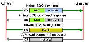
During this initiation, the client device indicates which information is going to be accessed from the server's object dictionary, which SDO type is used, and if the information is to be read or written. The server device acknowledges the inquiry and the client device then starts to transmit the first data segment. The normal transfer allows to communicate any amount of data in a segmented way. Each segment can carry up to seven byte of application data, as one byte of the CAN frame is required for protocol information. In normal SDO transfer (see figure) an unlimited number of segments and therefore of application data can be exchanged. 

To speed up an SDO transfer of small amounts of data (less or equal 4 byte), the expedited SDO transfer can be used. In such an SDO connection, the data is directly transferred during the initiation of the SDO connection. Speeding up the transmission of huge amounts of data can be achieved by supporting the SDO block transfer. During the block transfer, no single data segment (like during the normal transfer) but only a block of data (up to 127 segments) is confirmed by the receiver.

Device manufacturers should base their choice of SDO variant on the amount of data that a device is going to communicate.

SDO channels

A CANopen device may support SDO client or server channels. In case a device supports SDO client channels, the device is able to access the object dictionaries of other network participants.  By supporting server channels, device manufacturers give other network participants the opportunity to access object dictionary entries on their device. Device manufacturers must evaluate whether their device needs to access other devices (e.g. a controller that configures other network participants) or whether other devices have to access their device (e.g. for configuration purposes). After this evaluation, device manufacturers can assess how many SDO client and server channels will be required. The first SDO server channel is strictly predefined by the specification and has to be supported by all CANopen devices.

SDO parameter set

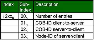
The SDO parameter sets are arranged in the object dictionary index range 12xxh. The SDO server channels are described in the range from 1200h to 127Fh. The parameter sets of the client channels have to be provided in the range from 1280Fh to 12FFh. A SDO parameter set contains the two communication object identifiers (COB-IDs) and the node-ID of the related communication partner. The COB-ID entries cover the CAN-Identifiers of the CAN frames used to transmit information in the direction "server to client" and vice versa.  


B. Process data object (PDO)

    Process data objects (PDOs) are used in CANopen for broadcasting high-priority control and status information. A PDO consists of a single CAN frame and communicates up to 8 byte of pure application data. Device designers have to evaluate the amount of process data that the device needs to receive and transmit. Based on the result of this evaluation process, they have to provide the related amount of receive and transmit PDOs within the device.

PDO parameter sets

In case a device is supposed to support the transmission/reception of a PDO, the corresponding parameter sets for this PDO have to be provided in the object dictionary of that device. A single PDO requires a set of communication parameters (PDO communication parameter record) and a set of mapping parameters (PDO mapping record).

Among others, the communication parameters indicate the CAN-Identifier that is used by this PDO, and the triggering event that prompts the transmission of the related PDO. The mapping parameters indicate which information of the local object dictionary is supposed to be transmitted and where the received information is to be stored.

The communication parameters for receive PDOs are arranged in the index range 1400h - 15FFh and for transmit PDOs in the range 1800h - 19FFh. The related mapping entries are managed in the index ranges 1600h -17FFh and 1A00h - 1BFFh.

PDO triggering events

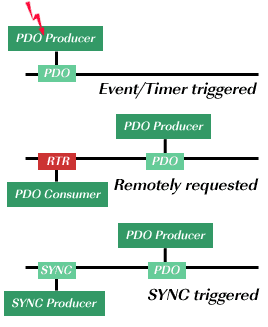
The following triggering events for PDOs are defined:

Event- or timer-driven: A device-internal event triggers the PDO transmission (e.g. when the temperature value exceeds a certain limit; event-timer elapses; etc.).

Remotely-requested: As PDOs consist of a single CAN data frame, they can be requested via remote transmission request (RTR).

Synchronous transmission (cyclic): The transmission of the PDO can be coupled to the reception of the SYNC message.

Synchronous transmission (acyclic): These PDOs are triggered by a defined device-specific event but transmitted with the reception of the next Sync message.

PDO mapping

PDO mapping defines which application objects are transmitted within a PDO. It describes the sequence and length of the mapped application objects. The mapping of the application objects is described in the related CANopen object dictionary entries for each PDO. CANopen distinguishes between three types of PDO mapping:

Static PDO mapping: In case static mapping is supported for a PDO, the content of the PDO is strictly predefined by the device manufacturer and cannot be changed via the CANopen interface.

Variable PDO mapping: Variable PDO mapping describes that the mapping entries of a PDO can be changed during NMT pre-operational state.

Dynamic PDO mapping: A device supports dynamic mapping if the PDO mapping entries in the CANopen object dictionary can be changed during NMT operational state as well.

PDO mapping procedures

In contrast to a strictly pre-defined mapping, device designers have the option of offering to change the mapping of the PDOs. In CANopen such a flexibly-adjustable PDO mapping capability is called variable or dynamic PDO mapping. In case variable or dynamic mapping is supported, the mapping entries of the PDO can only be changed by using the defined mapping procedure:

  1. Set PDO invalid by switching Bit 31 in the related COB-ID entry.
  2. Set PDO mapping invalid by writting 00h to sub-index 00h of the related mapping entries.
  3. Adjust the desired PDO mapping.
  4. Set sub-index 00h of the related mapping index to number of mapped objects.
  5. Switch PDO valid by means of Bit 31 in the related COB-ID entry.

C. Network management (NMT)

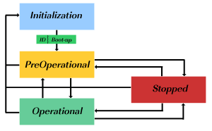
All CANopen devices must support the CANopen network management (NMT) slave state machine. The NMT state machine defines the communication behavior of a CANopen device. The CANopen NMT state machine consists of an Initialization state, a Pre-operational state, an Operational state, and a Stopped state. After power-on or reset, the device enters the Initialization state.

After the device initialization is finished, the device automatically transits to Pre-operational state and indicates this transition by sending the boot-up message. This way the device indicates that it is ready to work. A device that stays in Pre-operational state can start to transmit SYNC-, Time Stamp- or Heartbeat  messages if these services are supported and configured in the right way. In contrast to PDO communication that has to be disabled in this state, the device can communicate via SDO. PDO communication is only possible in the Operational state. During Operational state, the device can use all supported communication objects. A device that was switched to the Stopped state only reacts to received NMT commands. In addition, the device indicates the current NMT state by supporting the error control protocol during Stopped state. 

Initilization state

The Initialization state covers the three substates Initialising, Reset Application, and Reset Communication. During Initialising, the device starts up and initializes its internal parameters. The two substates Reset Application and Communication were introduced to enable partial reset commands. During Reset Application all parameters in the object dictionary range from 2000h to 9FFFh are set to the power-on or default values. After setting the power-on values, the NMT substate Reset Communication is entered autonomously. During the Reset Communication substate, the parameters of the communication profile (Index range 1xxxh) are set to their power-on/default values. After this state, the Initialization state is left.

NMT protocol

The NMT protocol is transmitted by the active NMT master in a CANopen network. The reception of the NMT protocol forces the CANopen device to transit to the commanded NMT state. The NMT protocol comes in a single CAN frame with a data length of 2 byte. The first byte contains the command specifier and the second contains the Node-ID of the device that has to perform the command (if this value is equal to 0, all nodes have to perform the commanded state transition). The NMT protocol comes with the CAN-Identifier 0, the highest prior CAN-ID in a CAN-based system.


D. Special Function Protocols

CANopen offers three specific protocols for generating a special network behavior:

  • The SYNC protocol enables synchronous network behavior.
  • The Time-stamp protocol is used for the adjustment of a unique network-time.
  • The Emergency protocol can be used to inform other network participants about device-internal errors.

Synchronisation (SNYC) protocol

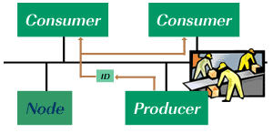
The SYNC protocol is transmitted periodically by the SYNC producer. The time period between two consecutive SYNC messages is the communication cycle period. The SYNC message is mapped to a single CAN frame with the identifier 80h according to the predefined connection set. By default, the SYNC message does not carry any data (DLC = 0).  Devices that support CiA 301 Version 4.1 or higher may optionally offer a SYNC message, which provides a 1 byte SYNC counter value. Therefore synchronous behavior of several devices can be coordinated more comfortably.

Emergency protocol

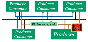
The Emergency messages are triggered by a device-internal error. The Emergency message, transmitted by the Emergency producer, is mapped to one single CAN frame, which covers up to eight byte of data. The data content is defined as a 1 byte Error register (Index 1001h of the local object dictionary), a 16-bit Emergency error code, and up to 5 byte of manufacturer-specific error information. By default, a device that supports the Emergency producer functionality assigns the CAN-Identifier 80h + (node-ID) to the Emergency message.  An Emergency message is transmitted only once per error event. As long as no new errors occur on a device, no further emergency messages are transmitted. Zero or more Emergency consumers may receive these messages and may initiate suitable, application-specific counter measures.

Time-stamp protocol

The Time-stamp protocol enables the user of CANopen systems to adjust a unique network time. The Time-stamp is mapped to one single CAN frame with a data length code of 6 byte. These six databytes provide the information "Time of Day". This information is given as milliseconds after midnight (Datatype: Unsigned28) and days since January 1, 1984 (Datatype: Unsigned16). The associated CAN frame has by default the CAN-Identifier 100h.


E. Error Control Protocols

Error control protocols enable the monitoring of a CANopen network. They comprise the Heartbeat-, Node-/Life-Guarding-, as well as the Boot-up protocol. The Heartbeat protocol is used to verify that all network participants are still available in a CANopen network and that they are still in their intended NMT FSA state. In old-fashioned CANopen systems, the CAN remote frame-based Node-/Life-guarding protocol is used for this purpose, instead of the Heartbeat protocol. CAN in Automation no longer recommends using CAN remote frame-based services. All error control protocols are based on the same CAN message with the CAN-ID 700h + Node-ID of the CANopen device that are to be monitored.

Heartbeat protocol

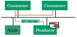
The Heartbeat protocol is a cyclically transmitted message that informs all heartbeat consumers of the availability of the heartbeat producer. In addition to the availability of the heartbeat producer, the heartbeat protocol provides the current NMT FSA state of the heartbeat producer. The cycle time for transmitting the Heartbeat message is configurable in the object dictionary index 1017h.

Boot-up protocol

The boot-up protocol represents a special type of an error control protocol. It is transmitted as the final action in NMT FSA state Initialisation, prior to enter the NMT FSA state Pre-operational. The reception of this message indicates that a new device has been registered to the CANopen network. The unintended reception of such a protocol during runtime either indicates a change in the network setup (e.g. due to the addition of a new CANopen device) or is considered a sign for an error condition (e.g. erroneous power supply of related CANopen device). The protocol uses the same identifier as any other error control protocol, such as e.g. the heartbeat protocol. The 1-byte data field has a fixed value of zero.

Node-/Life guarding protocol

Guarding is an outdated method of checking whether a guarded CANopen device is still working in the correct network state. As this is an RTR-based service, the Heartbeat protocol is used in new designs. In old-fashioned applications, the host controller triggers the error control information of the monitored CANopen devices via the CAN remote frame (RTR) for example. Each monitored CANopen device has to be triggered individually. The monitored device replies with a CAN data frame that indicates the current NMT FSA state.


Share:

ONLINE SHOP : PRODUK AUTOMATION

ONLINE SHOP : PRODUK AUTOMATION
________CITAYAM AUTOMATION________

Followers

View

Translate